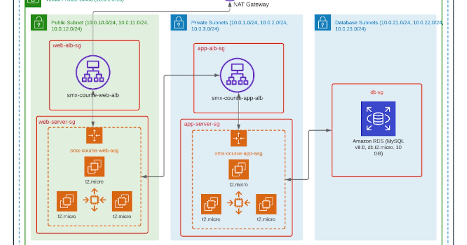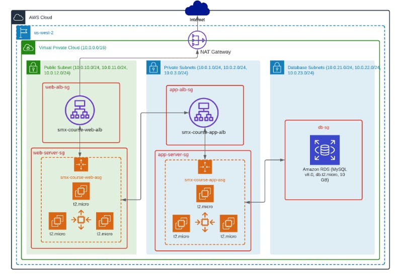
AWS 3-tier architecture has been a thing these days, a whole lot of people building it, making content about it and also making blogs on it like I am doing now :). So what exactly is it? It is decoupling our Application architecture into three logical tiers. The concept is to organize our application into three Tiers namely: Web/Presentation Tier, Application Tier, and The Data Tier. I'll be explaining each of these below.
Web/Presentation Tier - In this tier of the application architecture, this is where the user interface is deployed. For example, this is where your Nginx or Apache web server could be deployed to host your React Js or Vue Js frontend.
Application Tier - Here is the heart of the application where most of the process runs this is where business logic happens. In this tier data from the web tier is collected for processing for example your Django Backend, Node js or Php backend can reside here. This tier communicates with the data tier using APIs.
Data Tier - This is the database this is where data processed by the application tier is stored. This can be a relational database system such as PostgreSQL, MySQL, Oracle or even Mongo DB but for this example, we'll be using MySQL.
To show this great way of deploying an application on the cloud, I'll be deploying a LAMP (Apache web server with PHP and MySQL on Amazon Linux) application on AWS and a great tool that helped me accomplish this following best practice is Terraform. So what is Terraform?
Terraform is a sleek smooth and super cool Infrastructure as Code tool (IaC). This tool is a great DevOps tool that allows you to define your whole infrastructure on any cloud provider as code eliminating the nightmare of having to click the AWS management console always. This tool allows you to have full customization and control of resources on the cloud.
Now enough with talking let's get into coding. To deploy a 3 tiered Architecture design application on AWS I'll try my possible best to explain the services and their uses. I'll give you a hack, the most Vital and Important component in this architecture design is networking. The networking component is very sensitive as it is the weakest and strongest part of the application's architecture. This terraform deployment handles it. Now the prerequisites to deploying this are listed below:
An AWS account
AWS access and secret keys configured
Basic Knowledge of AWS and Terraform
If you'd love to follow along you can kindly look at the github repo for this demo project ( github.com/realexcel2021/3-tier-Architectur..)
Step 1: Create a main.tf file in the folder you wish to write terraform code and configure the provider and the region you wish to deploy your whole architecture in my code I'll be using us-east-1.

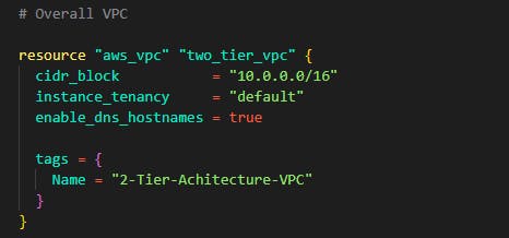
Step 2: Create the VPC where all resources can be isolated. This is your fragment of AWS. Make sure to enable DNS hostnames.
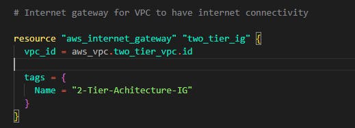
.Step 3: Create an Internet gateway to enable Internet access to resources and servers in that VPC. Note to attach it to the VPC using the vpc_id attribute.
Step 4: In this step, we'll be creating public and private subnets for the architecture design. To accomplish this, we'll b using modules, a terraform code feature that allows us to reuse code and only change its parameters. See this like your python or javascript functions. Now create a folder named modules and ass another folder in the newly created folder. Name the new sub-folder subnets so, in the end, you'll have something like this: Kindly ignore the ec2 folder we'll come to that.

Now change the directory into the newly created folder modules/subnet and create three files namely: main.tf, var.tf, output.tf In the main.tf file, we'll be adding the module code for the subnets. In this example, we'll be creating 9 subnets, 3 for the web/presentation tier, 3 for the application tier, and 3 for the data tier. See this module code like the function that creates subnets for us. In this case reusable code for subnets. Now in modules/subnet/main.tf put in the following code
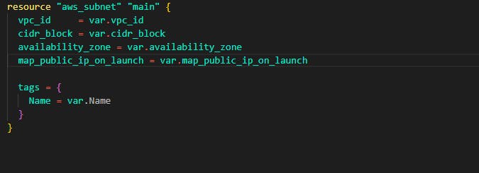
In modules/subnet/var.tf add the following code
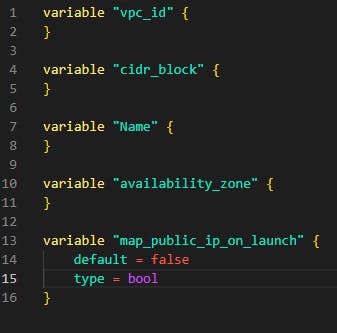
In the modules/subnet/output.tf add the following. Note that this output file is very important as it exposes the data needed in this reusable codebase.

Step 5: In this step, we'll create subnets from the module we created in Step 4. Head back to the main project folder and create a subnet.tf file. In this file, we'll be using modules to create 9 subnets. For public subnets for web tier in our VPC, add the code below in the file
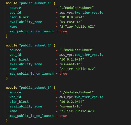
For private subnets for application tier in the VPC add the following code still in the same file
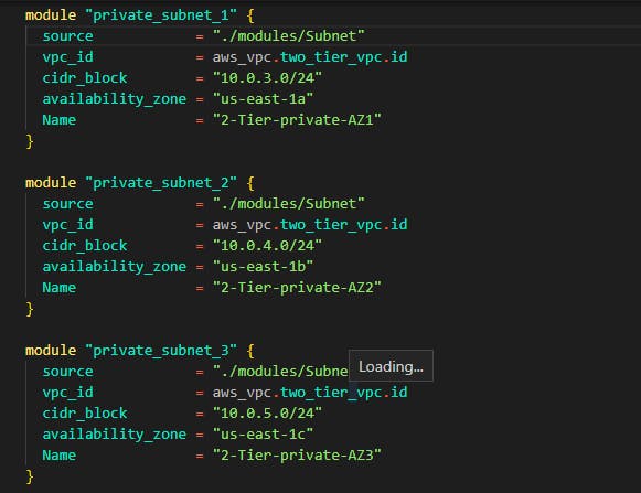
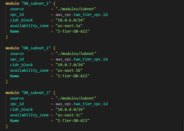
The same process is for data tier subnets you can see how the module source is targeted using the path we created /modules/subnet
Step 6: You have successfully written code for subnets in the VPC next up is to create route tables and associate those route tables to these subnets. For this demo, we'll be creating 3 route tables and then placing these 9 subnets. Now head over to the main.tf file where we wrote the VPC and Internet gateway code and add the following route tables
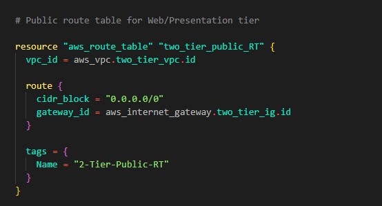
Now in the main.tf file, add the following code for the web tier subnets route table
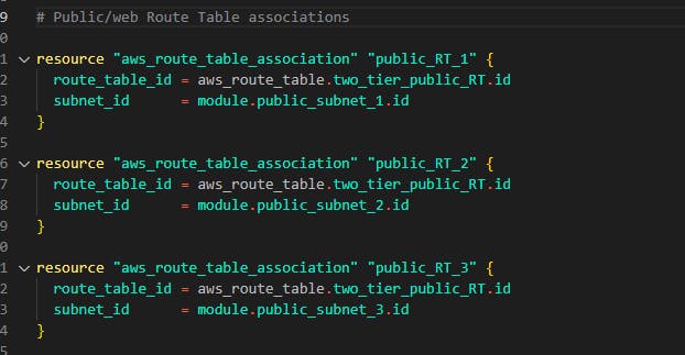
Next attach the 3 public subnets for web tier we created using modules.
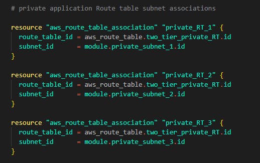
Next we'll do same for private subnets which is subnet for application tier
The same thing goes for data tier
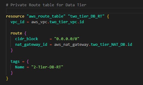
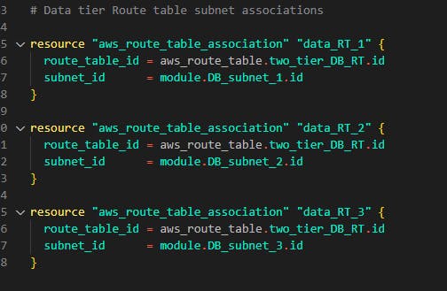
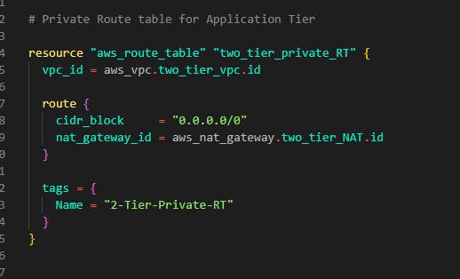
Step 7: In this step, we'll be adding NAT gateways. The NAT gateway is useful for our resources in the private subnet to have connections to services outside the VPC for example let's say we need to update our Application Tier servers and it is deployed in the private subnet without an internet connection how do we go about this? The NAT gateway is responsible for this. Now to build this with terraform, still on that same main.tf file where all our networking resides, add the following code for our application tier
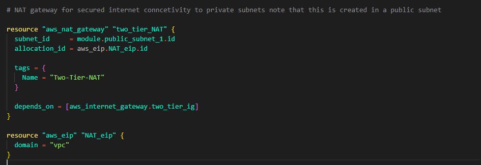
Note that the NAT gateway is created with an Elastic IP address which is created below it and attached using the allocation_id note that the NAT gateway is attached to one public subnet for a secure internet connection.
Also, note that each NAT gateway created in this step is already targeted by route tables for each tier. This is to attach all the subnets under that specific route table to the NAT gateways we create here.
Next up is NAT gateway for the data tier
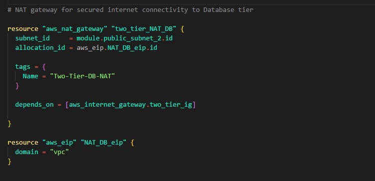
If you've gotten to this step then a big congrats to you!! you have successfully completed the networking section of the Architecture now is time to deploy servers and resources on this networking we have provisioned.
Step 8: But before deploying resources, why don't we, first of all, configure security for these resources we are creating on the deployment? Create a securtiy_groups.tf file and let's add security group rules for the web tier
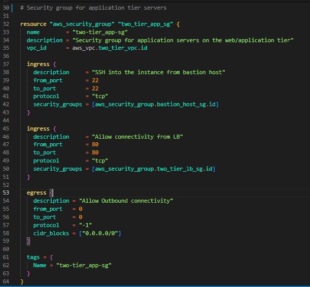
In this security group, we gave SSH access from the bastion host (We'll come to that in a bit) and them allowed connectivity from the Load Balancer (Which we will create later on). We allowed all outbound connectivity so resources can communcate with the NAT gateway and have internet connection even in the private subnet.
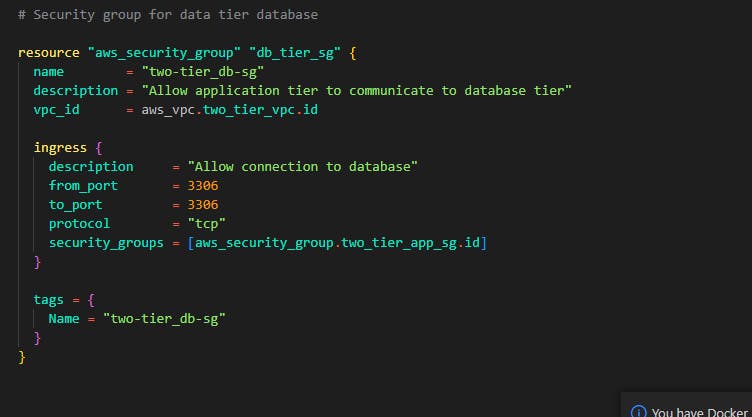
We'll create a security group for the data tier too. This time in the data tier security group, we'll allow inbound rule of 3306. This is important as MySQL default port is 3306. Note that the inbound rule is only allowed from the application ier security group, this is very important for security reasons making our database secured and not allowing any connections apart from the application tier is gold when it comes to security in this Archtecture.
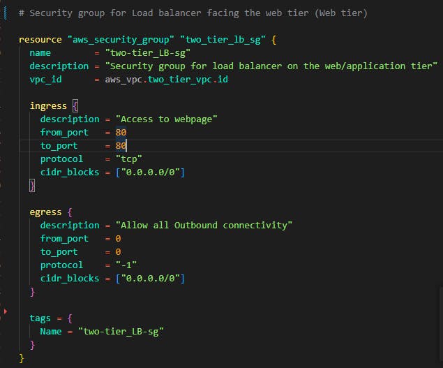
Another security group is for the web tier. Now for this demo, the load balancer facing the application tier serves as the Web tier. Let's configure the security group for the load balancer.
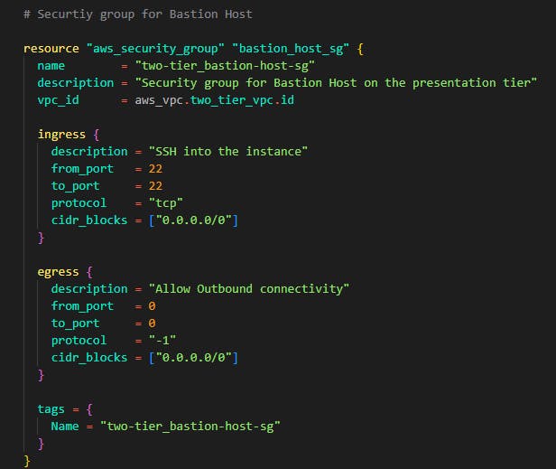
Now finally we'll be creating a security group for the bastion host. What is this bastion host I've been talking about? The bastion host is the machine/server we will use to connect to our application tier servers, the application tier servers are in the private subnet so they cannot accept inbound rules from the internet only from the local network within the VPC. The bastion host is how we SSH into the application servers and make changes or updates or whatever.
As you can see the bastion host accepts all port 22 connections from all IP addresses. This isn't safe as you are to edit that cidr blocks to your computer's IP address but for the sake of this demo, we'll allow it. Port 22 is to allow SSH connections to the bastion host instance.
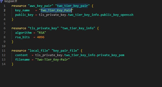
Step 9: In step, we'll create the server for the application tier. For this demo, we'll be choosing t2.micro as our instance type and the Amazon Linux 2 ami. Create a file and name it keypair.tf The code below creates a key pair and saves it in the working directory. This key pair will be used in both the Bastion host server and the application tier servers.
Next, create another file and name it ec2.tf in this file, we'll start by writing code for the application tier servers below you can see the ami chosen and t2.micro for the instance type. Note the vpc_security_group_ids in this attribute, we targeted the security group for the application tier and the key_name is targeting the key name of the key pair we created. Note that the aws_autoscaling_group resource has an attribute named target_group_arns. This attribute is what allows any instance created in that auto-scaling group to be placed in the load balancer's target group which we will create in the step 12.
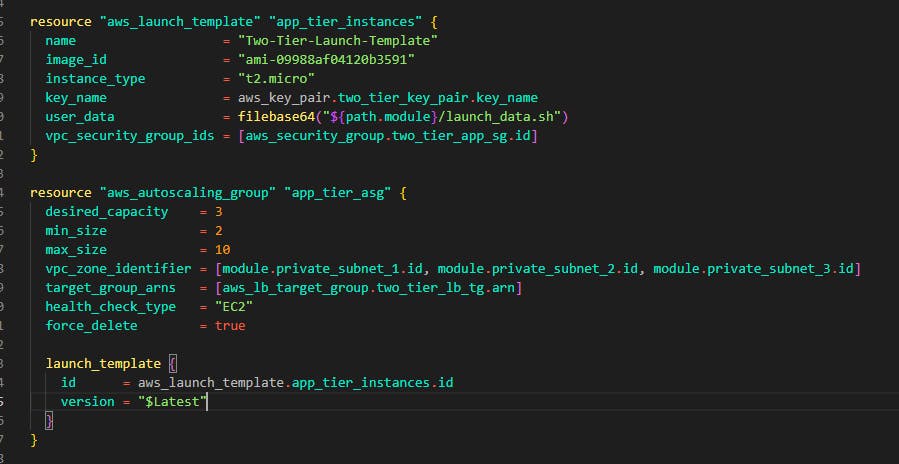
Below the launch template, we have an auto-scaling group. This helps in scaling out and scaling in instances. In this case, the Instances are increased based on load. You can see that the maximum size is 10. Also not that all three application subnets are added in the vpc_zone_identifier attribute.
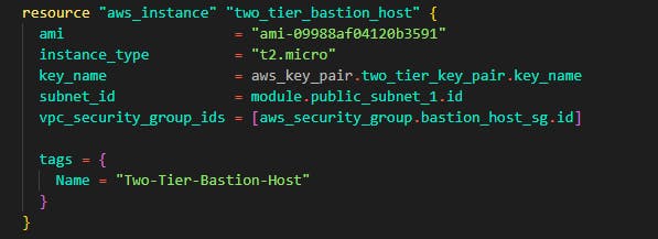
Step 10: Still in the same ec2.tf file, we'll create the Bastion host instance that has access to connect to the application tier instances. The same ami is used for the bastion host and one of the public subnets is added in the subnet_id attribute. The same key is used in the bastion host. Note that the security group we created for the bastion host is targeted using the vpc_security_group_ids.
Step 11: If you noticed there is a user_script attribute that was used in the launch template, let's give the application tier the script to install useful dependencies and packages. Create a file and name it launch_data.sh in that file, paste the script below:
#!/bin/bash

sudo yum update -y

sudo amazon-linux-extras install -y lamp-mariadb10.2-php7.2 php7.2

sudo yum install -y httpd mariadb-server

sudo systemctl start httpd

sudo systemctl enable httpd

sudo usermod -a -G apache ec2-user

sudo chown -R ec2-user:apache /var/www

sudo chmod 2775 /var/www && find /var/www -type d -exec sudo chmod 2775 {} \;

find /var/www -type f -exec sudo chmod 0664 {} \;

sudo yum install php-mbstring php-xml -y

sudo systemctl restart httpd

sudo systemctl restart php-fpm

cd /var/www/html

wget https://www.phpmyadmin.net/downloads/phpMyAdmin-latest-all-languages.tar.gz

mkdir phpMyAdmin && tar -xvzf phpMyAdmin-latest-all-languages.tar.gz -C phpMyAdmin --strip-components 1

rm phpMyAdmin-latest-all-languages.tar.gz
This script file will install the web server which is Apache and PHP on the application tier server it will also install other packages and dependencies needed to connect the application tier to the data tier.
Step 12: Now we have multiple instances in our application tier and each of them has its own IP addresses plus they are in private subnets, so how do users interact with the application? This is where load balancers come in. We'll place the load balancer in front of the application tier and give the right permissions to it to communicate with the instances.
Create a file and name it loadbalancer.tf inside the file, add the following code
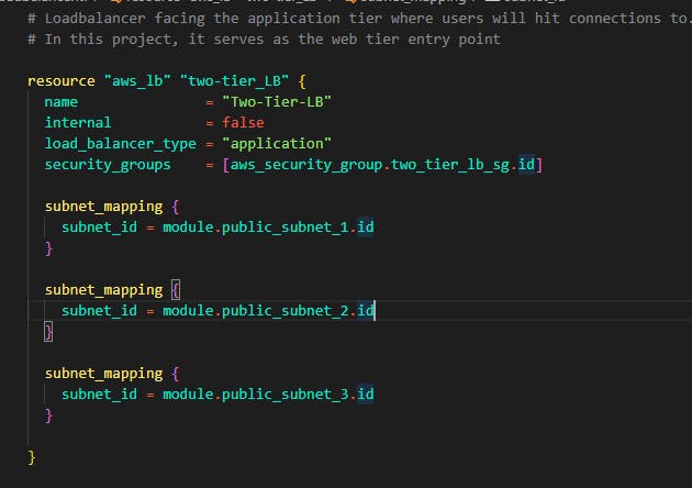
You can see that in the security_groups attribute we targeted the security group we created for the web tier. Now in the subnet_mapping block, we target the 3 public subnets we created for the web tier.
Note that this load balancer now needs a target group and that target group should have a list of the instances created by the auto-scaling group. Paste in the code below still in the same loadbalancer.tf file. This will create the target group and also a loadbalancer listener that connects the port 80 to the instances in the target group to the load balancer.
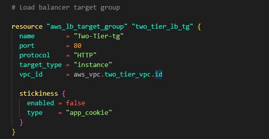
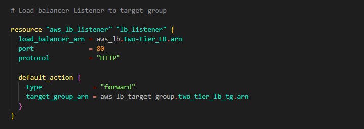
Step 13: If you've gotten to this step, congrats you have successfully written code for the application tier and the web tier now as you know, the final thing left out is the data tier (database). Let's write some code to deploy our database. First of all, let's configure a group with all the 3 subnets for the data tier. Create a file and name it rds.tf Let's add the subnet by adding the code below into the file

Now finally, Let's write some code for the database. For this demo, we'll be using a MySQL database running version 8.0. We'll be setting the password management to be managed by AWS in the Key management system. This is to avoid hard coding and writing passwords in code which is BAD practice.
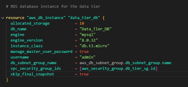
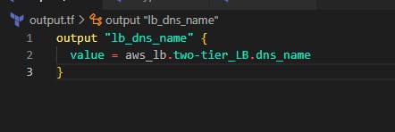
Finally, let's add another file. terraform allows us to create an outputs file, this file will print out every parameter we define in the output file after deployment for example, we created a load balancer and we would love to see the DNS name for the load balancer so we can access the frontend/web tier of the application.
Add a file and name it output.tf in this file, we'll add a block of terraform code that will output the DNS name for the load balancer that was created for the web tier.
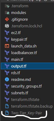
With this written in the rds.tf file we have completed the data tier for this demo at the end of this, you should have a folder structure like this: Kindly ignore the .gitignore file and other terraform config files. We'll get to them.
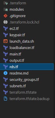
If you have completed this code to this stage, a big congrats to you. You have successfully written code for a demo 3-tier architecture on AWS now let's create this on AWS and deploy this infrastructure on the cloud.
Now to deploy any infrastructure as code using Terraform, you have to pass some commands using any command line interface. Having met the prerequisites of having Terraform installed on your machine and having configured your AWS access keys, run the following commands in the working directory where you wrote all the terraform files.
Terraform is so cool that it allows you to pass a command that checks for syntax errors you have made anywhere in your code. So let's run that first. The command for this is terraform validate. Now head over to any terminal or command line on your Windows or Mac and change the directory to your project folder and pass the command. If you get a response like this you have a correct configuration codebase.

If you get any errors after passing that command, check your code and do some debugging with the code here.
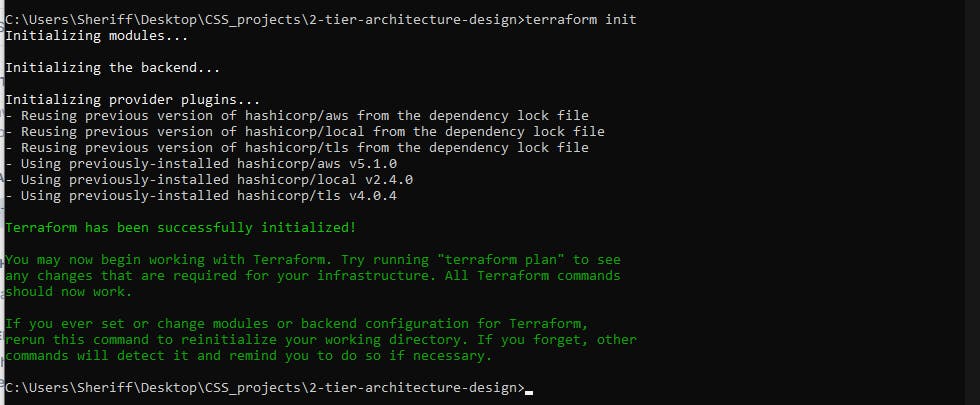
Next, we'll install the provider we choose so we can deploy to that provider remember we choose AWS as our provider. Now passing the next command will install all providers, and dependencies and configure all modules we used in the code so we can deploy to the cloud, the command here is terraform init . After passing the command, you should have a response like this image below. If you get a response like this then you are ready to deploy your code to AWS.
Let's see all the resources we will be creating from the code we have written. Now terraform allows us to just see all resources we will create without creating them the command is terraform plan This command will list out all the resources that are to be created from the code, these are the resources on AWS.
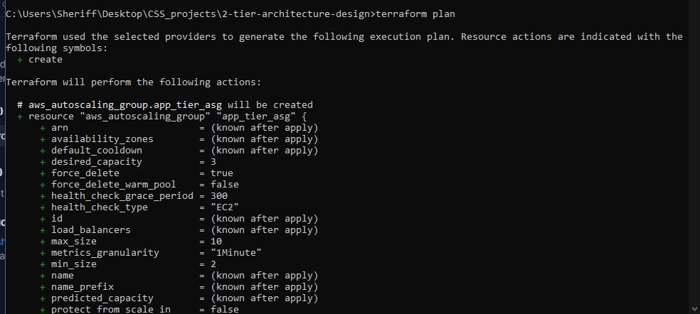
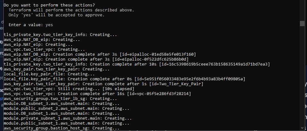
The configuration looks good so we are now ready to deploy. To deploy this, the command to do this is terraform apply now let's run this command and see how terraform performs magic into our AWS account. This command first shows us what we are going to deploy exactly what terraform plan does and then it asks us for a prompt just type yes and it should start creating those resources in your AWS account

As you can see, the Load balancer DNS name is exposed to us after the deployment of all the resources. Now let's check that endpoint in the browser and see if the PHP application and the web server got installed.
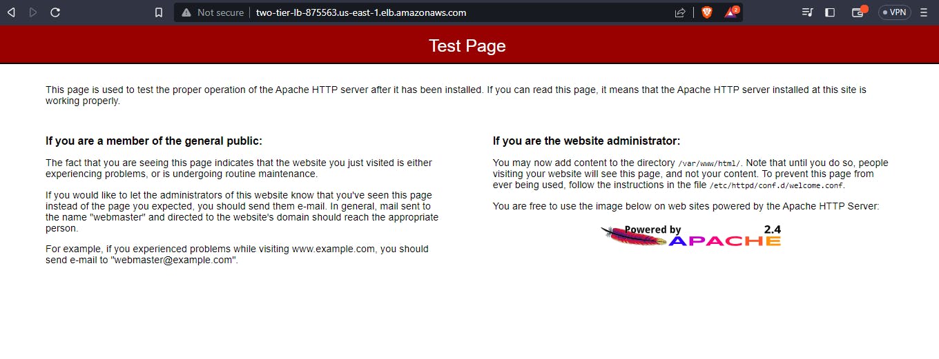
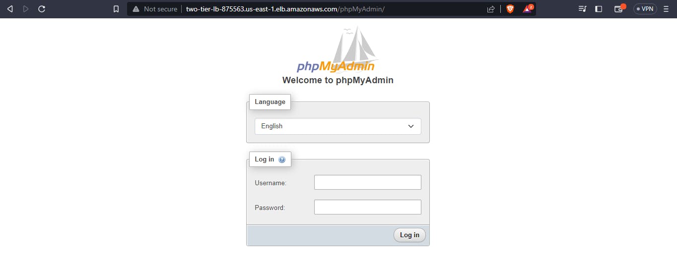
In the photo above, you can see the web server installed. Next let's check the PHP my admin if it was installed on the servers, to check this, add /phpMyAdmin after the load balancer's link and you should have a login page that looks like this:
Now let's check AWS and see the services provisioned: the servers, subnets database and the route tables.

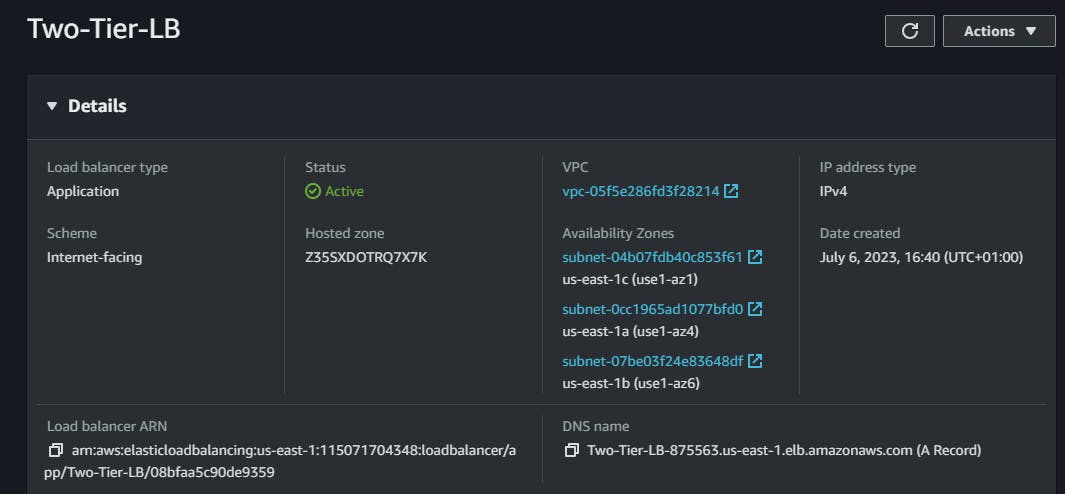


All services were deployed and successfully configured. Note that when you check your project folder, you'll find the Key Pair file generated. You can use this key pair to connect to all the servers. To connect to the servers in the private subnet, first connect to the bastion host from your local machine and then create a .pem file and paste the content of this generated key pair file. Then you can use the key inside the bastion host to connect to those application tier servers using the private IP address.
Now let's clean up what we've built to avoid unnecessary billing from AWS. Now terraform is so cool that we do not need to go to the console and delete each resource one by one instead we can just delete the whole architecture resources with one command. Head back to your terminal or command prompt in your working directory, type in the command terraform destroy this will delete all resources. When it asks you for a prompt type yes

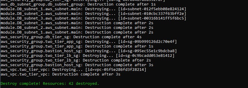
As you can see above, all resources we created just got deleted with one single click!
Thank you very much for following with this article. I know it's not perfect and has many flaws because this is my first article so feel free to reach out to me on Twitter if you have any questions or corrections for me. Thank you very much!
